Unraveling the Secrets of Servo Motor Design
Imagine a tiny dancer, responding instantly to every cue, moving with precision and grace. That, in essence, is the magic of a servo motor. But what gives these miniature marvels their incredible responsiveness? The answer lies within their intricate design, a blueprint captured in the servo motor construction diagram. Understanding this diagram is like unlocking the secrets of this electromechanical choreography.
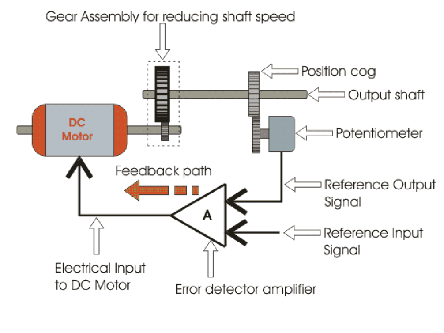
So, what exactly is a servo motor construction diagram? It’s a visual representation of the internal components of a servo motor, showing how they are interconnected and how they work together to produce controlled motion. Think of it as a map that guides you through the inner workings of this remarkable device. From the humble DC motor at its core to the sophisticated control circuitry that governs its every move, the diagram reveals the intricate dance between electrical signals and mechanical movement.
Peering into the history of servo motor diagrams, we find a fascinating evolution. Early diagrams were simple, reflecting the simpler construction of early servo motors. As technology advanced, so too did the complexity of the diagrams, mirroring the incorporation of feedback mechanisms, integrated circuits, and more sophisticated control algorithms. Today, servo motor diagrams can be quite detailed, reflecting the precision and versatility of modern servo motors.
The importance of understanding these diagrams cannot be overstated. For engineers and technicians, a servo motor construction diagram is an invaluable tool for troubleshooting, maintenance, and even design. It allows them to identify specific components, understand their function, and diagnose potential issues. For students and hobbyists, the diagram provides a crucial window into the principles of electromechanical systems and the intricacies of control engineering.
One of the main challenges related to understanding servo motor diagrams is the sheer density of information they often contain. Deciphering the various symbols, abbreviations, and technical terms can be daunting for the uninitiated. However, with a little patience and a systematic approach, anyone can learn to read and interpret these diagrams effectively. The key is to break down the diagram into its constituent parts and focus on understanding the function of each component individually, then piecing them together like a puzzle.
A typical servo motor diagram will illustrate the motor itself, including the stator, rotor, and commutator. It will also depict the gearbox, which translates the motor's rotation into the desired output motion. Crucially, the diagram will also show the control circuitry, including the potentiometer, which provides feedback on the motor's position, and the integrated circuit, which compares the desired position with the actual position and adjusts the motor's output accordingly.
Benefits of understanding a servo motor's construction diagram include: improved troubleshooting, easier selection of the correct servo for a specific application, and a deeper understanding of how these devices work. For example, knowing the gear ratio from the diagram can help determine the output torque and speed, which are critical factors in robotic applications.
If you're trying to learn more, consider resources like the Arduino Project Hub, online tutorials on robotics websites, or textbooks on control systems and mechatronics. These resources often provide detailed diagrams and explanations of servo motor operation and construction.
Advantages and Disadvantages of Detailed Servo Motor Diagrams
| Advantages | Disadvantages |
|---|---|
| Improved Troubleshooting | Can be complex and overwhelming for beginners |
| Better Component Identification | Requires some technical knowledge to fully understand |
| Facilitates Design and Modification | May not be readily available for all servo motor models |
FAQ:
What is the purpose of a servo motor construction diagram? - It provides a visual representation of the internal components and their connections.
What are the main components shown in the diagram? - Typically, the motor, gearbox, potentiometer, and control circuitry.
Why is the potentiometer important? - It provides feedback on the motor's position, enabling precise control.
How does the diagram help with troubleshooting? - It allows for identification of faulty components.
Where can I find servo motor construction diagrams? - Datasheets, online tutorials, and textbooks.
What is the role of the gearbox? - It modifies the motor's output speed and torque.
How does the control circuitry work? - It compares the desired position with the actual position and adjusts the motor accordingly.
What are some common symbols used in the diagrams? - Symbols for resistors, capacitors, integrated circuits, and motors.
In conclusion, the servo motor construction diagram is a powerful tool for anyone working with these versatile devices. From engineers to hobbyists, understanding the blueprint of a servo motor unlocks a world of possibilities, enabling us to harness the precision and power of these miniature marvels. While the diagram may seem complex at first glance, with a little effort, anyone can learn to decipher its secrets. This knowledge empowers us to troubleshoot, design, and innovate, pushing the boundaries of what's possible with servo motor technology. So, dive into the diagram, explore its intricacies, and unleash the power of precise motion control. The future of robotics and automation awaits!
Remembering the bulge a tribute to the battle of the bulge monument
Ac compressor vacuum pump deep dive
Unleash the holy grail war your guide to the fate stay night original game download


