Unlocking the Secrets of the 4-Pole Starter Solenoid Wiring Diagram
Understanding the intricacies of a 4-pole starter solenoid wiring schematic is crucial for anyone working with electrical systems, especially in automotive applications. This seemingly small component plays a vital role in cranking your engine, and a faulty connection or incorrect wiring can lead to starting issues or even complete failure. This comprehensive guide will delve into the world of 4-pole starter solenoid wiring, providing a clear understanding of its function, implementation, and troubleshooting.
The starter solenoid acts as a powerful relay, controlled by the ignition switch, allowing a large current to flow to the starter motor. The 4-pole configuration offers more versatility, often incorporating features like a separate terminal for accessories or safety interlocks. Mastering the four-pole starter solenoid wiring configuration opens doors to understanding a wider range of electrical systems.
Historically, starter solenoids have evolved from simple mechanical switches to the more robust and reliable electromagnetic relays we use today. The development of the four-pole configuration provided additional control and functionality, allowing for more complex starting systems. This evolution has been driven by the increasing complexity of vehicle electrical systems and the need for enhanced reliability and safety.
The importance of a correctly wired 4-pole starter solenoid cannot be overstated. It ensures the proper functioning of the starting system, a critical component for any internal combustion engine vehicle. A faulty starter solenoid connection can lead to various problems, including a clicking sound when turning the key, a completely dead starter, or even damage to other electrical components.
Common issues with 4-pole starter solenoid wiring include loose connections, corroded terminals, faulty solenoids, and incorrect wiring. These issues can be diagnosed and resolved through careful inspection, testing, and following the appropriate wiring diagram.
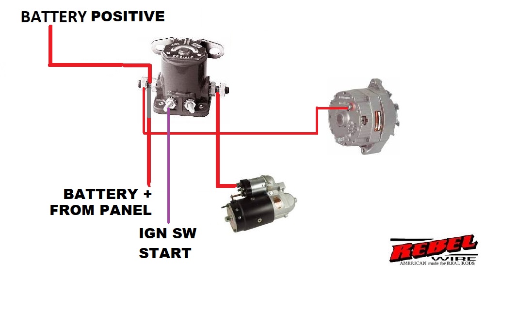
A 4-pole starter solenoid wiring diagram is a visual representation of the electrical connections between the solenoid, battery, ignition switch, and starter motor. It shows the path of the current flow and the function of each terminal. For example, one terminal connects directly to the battery's positive terminal, while another connects to the starter motor. Two additional terminals typically handle the ignition signal and accessory power.
One benefit of a 4-pole starter solenoid is its versatility, allowing for separate control of accessories or safety systems. For example, a 4-pole setup allows powering an electric fuel pump when the starter is engaged, ensuring adequate fuel delivery during starting. Another benefit is increased safety, as the additional terminals can be used for interlocks, preventing the starter from engaging unless certain conditions are met, such as the transmission being in neutral or park.
If you suspect a faulty starter solenoid, begin by checking the connections for looseness or corrosion. Next, test the solenoid by using a multimeter or a test light to check for continuity and voltage at the appropriate terminals. If the solenoid is faulty, replace it with a compatible unit.
Ensure all connections are clean and tight. Verify the correct wire gauge for each connection. Double-check the wiring diagram specific to your vehicle or application.
Step 1: Disconnect the negative battery cable. Step 2: Locate the starter solenoid. Step 3: Identify the terminals using the wiring diagram. Step 4: Connect the wires according to the diagram. Step 5: Reconnect the negative battery cable. Step 6: Test the starter.
Advantages and Disadvantages of 4-Pole Starter Solenoid
| Advantages | Disadvantages |
|---|---|
| Versatility for accessory control | Slightly more complex wiring |
| Enhanced safety features | Potential for more connection points to fail |
| Improved starting system reliability | Requires specific wiring diagrams |
FAQ
What is the purpose of a 4-pole starter solenoid? - It acts as a heavy-duty relay, controlling the high current to the starter motor.
How do I test a 4-pole starter solenoid? - Use a multimeter or test light to check voltage and continuity at the various terminals.
In conclusion, understanding the 4-pole starter solenoid wiring diagram is essential for maintaining and troubleshooting electrical systems. Its versatility, safety features, and reliability make it a critical component in many applications. By following the best practices, troubleshooting steps, and utilizing the available resources, you can ensure the smooth operation of your starting system and avoid potential issues. This knowledge empowers you to confidently work with electrical systems and ensures that you can diagnose and fix problems quickly and efficiently. Take the time to study the diagrams, understand the function of each terminal, and always prioritize safety when working with electrical components. Your understanding of this small but vital component will significantly contribute to your ability to maintain and repair a wide range of electrical systems.
Seal your bond the ultimate guide to matching best friend tattoos for 2
Decoding data mastering measurement with metrics and standard tool sets
Rocky 4 apollo creed fights ivan drago a cinematic showdown


