Unlocking the Secrets of Phasor Diagrams: A Comprehensive Guide
Imagine a spinning arrow, a visual whisper of the unseen forces at play in the electrical world. This is the essence of a phasor diagram, a graphical representation of alternating current (AC) circuits that allows us to grasp the intricate dance of voltage and current. But how do we decipher this elegant visual language? This journey into the heart of phasor diagrams will illuminate their power and reveal their secrets.
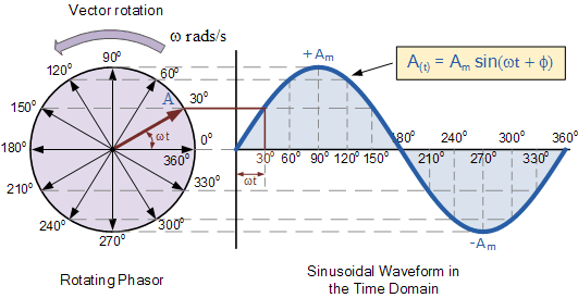
Phasor diagrams are not mere static images; they are dynamic snapshots of a constantly evolving electrical system. They capture the sinusoidal nature of AC, representing voltage and current as rotating vectors, or "phasors." These phasors have a magnitude corresponding to the peak value of the AC quantity and an angle representing its phase shift relative to a reference. Understanding this interplay of magnitude and phase is the key to unlocking the information encoded within the diagram.
The concept of visualizing AC quantities using phasors emerged from the need to simplify complex AC circuit analysis. Before phasor diagrams, calculations involving sinusoidal functions were cumbersome and time-consuming. Charles Proteus Steinmetz, a pioneering electrical engineer, is credited with popularizing the use of phasors in the late 19th century. His work revolutionized AC circuit analysis, paving the way for the widespread adoption of AC power systems.
The fundamental challenge in analyzing AC circuits lies in the constantly changing nature of voltage and current. Unlike DC circuits, where values remain steady, AC circuits involve sinusoidal variations that introduce the concept of phase difference. Phasor diagrams address this challenge by representing AC quantities as vectors, allowing us to visualize and analyze these phase relationships.
Interpreting a phasor diagram involves understanding the meaning of the vector's length and angle. The length of the phasor represents the magnitude of the AC quantity (voltage or current), while the angle represents the phase shift relative to a reference phasor. The reference phasor is typically drawn along the positive x-axis. A positive angle indicates a leading phase, while a negative angle indicates a lagging phase.
One of the primary benefits of using phasor diagrams is the simplified visualization of phase relationships between voltage and current. This visualization allows engineers to quickly determine whether a circuit is inductive, capacitive, or purely resistive. For instance, in a purely resistive circuit, the voltage and current phasors are aligned, indicating zero phase difference. In an inductive circuit, the current phasor lags behind the voltage phasor, while in a capacitive circuit, the current phasor leads the voltage phasor.
Another key advantage of phasor diagrams is their ability to simplify complex calculations. By representing AC quantities as vectors, we can use vector addition and subtraction to determine the resultant voltage or current in a circuit. This graphical approach eliminates the need for tedious trigonometric calculations, significantly speeding up the analysis process.
Furthermore, phasor diagrams are invaluable for understanding the behavior of AC circuits under different frequency conditions. By analyzing the changes in phasor magnitudes and angles as the frequency varies, we can gain insights into the circuit's impedance characteristics and resonant frequency.
To effectively interpret a phasor diagram, follow these steps: 1. Identify the reference phasor (usually along the positive x-axis). 2. Determine the magnitude of each phasor by measuring its length. 3. Measure the angle of each phasor relative to the reference phasor. 4. Analyze the phase relationships between different phasors to understand the circuit's behavior.
While phasor diagrams are powerful tools, they do have limitations. They primarily apply to steady-state AC circuit analysis and don't readily capture transient behavior. Additionally, they become more complex to interpret in circuits with multiple frequency components.
In conclusion, phasor diagrams are indispensable tools for anyone working with AC circuits. They provide a visual language for understanding the complex interplay of voltage, current, and phase, simplifying analysis and enabling engineers to design and optimize electrical systems effectively. By mastering the art of phasor diagram interpretation, we gain a deeper understanding of the electrical world and unlock the potential of AC power.
The allure of a silhouette silueta de hombre sentado
Finding peace and guidance exploring the power of post prayer supplications
The pale blue dot pondering lunar photography and our cosmic context


