Unlocking Hydraulic Power: Mastering Schematic Symbols
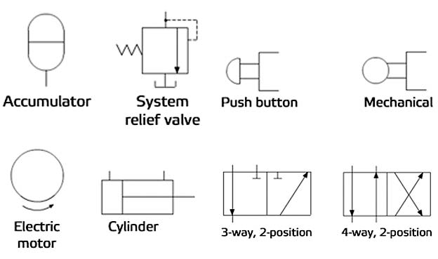
Ever wonder how those massive excavators or nimble forklifts manage to exert such incredible force? The secret lies within their hydraulic systems, complex networks of fluid power harnessed through carefully engineered components. To decipher these powerhouses, you need a key: understanding hydraulic system drawing symbols. These symbolic representations are the language of hydraulic design, allowing engineers and technicians to communicate complex ideas clearly and concisely.
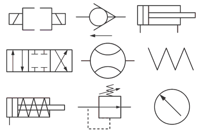
Imagine trying to build a house without blueprints. Chaos, right? Similarly, designing and maintaining a hydraulic system without a clear schematic is a recipe for disaster. Hydraulic schematic symbols provide a standardized visual shorthand, representing everything from pumps and valves to actuators and filters. They provide a roadmap for understanding how fluid flows through the system, enabling efficient troubleshooting and modification.
These symbols have a rich history, evolving alongside the development of hydraulic technology itself. Early schematics were often rudimentary, with variations in representation depending on the manufacturer or even the individual engineer. The need for standardization became clear as hydraulic systems grew more complex. Organizations like ISO (International Organization for Standardization) developed standards for hydraulic symbols, ensuring a common language for engineers worldwide.
Standardization is crucial for several reasons. First, it promotes safety. A misinterpretation of a symbol could lead to incorrect assembly or maintenance, potentially causing hazardous situations. Second, it facilitates collaboration. Engineers from different backgrounds can easily interpret a standardized schematic, streamlining design and troubleshooting processes. Third, standardization improves efficiency. By using a consistent set of symbols, time is saved in both design and training.
A key issue related to hydraulic schematic symbols is keeping up with technological advancements. As new components and technologies emerge, corresponding symbols must be developed and standardized. This ongoing process requires collaboration within the engineering community to ensure clarity and consistency.
A simple example of a hydraulic symbol is the rectangle representing a reservoir. Variations on the rectangle, such as adding lines or shapes within it, can indicate specific features like a strainer or a return line connection. Understanding these variations is essential for interpreting the entire schematic.
One major benefit of using these symbols is the enhanced communication they provide. A properly drawn schematic eliminates ambiguity, ensuring everyone involved in the project is on the same page. For example, a symbol clearly indicating a pressure relief valve allows technicians to quickly identify and inspect this critical safety component.
Another benefit is simplified troubleshooting. When a system malfunctions, the schematic provides a visual guide to trace the problem. By following the flow of fluid as depicted by the symbols, technicians can isolate faulty components much faster than they could without a clear diagram. This saves valuable time and resources.
Lastly, these standardized symbols facilitate efficient design. Engineers can quickly lay out a system using these visual building blocks, experimenting with different configurations and optimizing performance before any physical components are assembled. This allows for faster prototyping and reduced development costs.
A simple action plan for working with hydraulic schematics is to first familiarize yourself with the basic symbols. Then, practice reading existing schematics to gain a better understanding of how the symbols are used in context. Finally, try creating your own simple schematics to solidify your knowledge.
Advantages and Disadvantages of Standardized Hydraulic Symbols
| Advantages | Disadvantages |
|---|---|
| Clear Communication | Requires Initial Learning |
| Simplified Troubleshooting | Potential for Misinterpretation if not standardized |
| Efficient Design | Ongoing need for updates and standardization |
Best Practices:
1. Always use standardized symbols.
2. Label all components clearly.
3. Indicate flow direction with arrows.
4. Maintain a consistent scale.
5. Keep the schematic clean and uncluttered.
FAQ:
1. What does a circle with an arrow represent? A pump.
2. What does a triangle represent? A valve.
3. How is a cylinder represented? By a rectangle with a piston rod.
4. What is the symbol for a filter? A trapezoid.
5. Where can I find a complete list of hydraulic symbols? ISO 1219-1.
6. How do I interpret a complex hydraulic schematic? Break it down into smaller circuits.
7. What software can I use to create hydraulic schematics? Various CAD software packages.
8. What is the importance of consistent line thickness in a schematic? It helps differentiate between main lines and pilot lines.
In conclusion, mastering hydraulic system drawing symbols is like learning the alphabet of fluid power. These symbols are essential for anyone involved in designing, building, maintaining, or troubleshooting hydraulic systems. They provide a universal language that fosters clear communication, simplifies complex concepts, and empowers efficient problem-solving. By understanding and utilizing these symbols effectively, you can unlock the full potential of hydraulic power and ensure the safe and efficient operation of these powerful systems. Start learning today and empower yourself with the knowledge to tackle any hydraulic challenge! Invest the time to become fluent in this visual language, and you'll reap the rewards in increased efficiency and improved understanding of these powerful systems. Your journey into the world of hydraulics begins with a single symbol. Take the first step and unlock a world of power.
What does the airplane emoji mean decoding the digital skies
Urgent care bensalem pa
Journey through the unrivaled tang sect with huo yuhao


