Unlocking Circuits: Understanding Diode Symbols
Imagine trying to navigate a bustling city without street signs – chaos, right? Similarly, in the intricate world of electronics, schematic symbols for diodes act as crucial signposts, guiding us through the flow of electricity. These seemingly simple symbols hold a wealth of information, essential for designing, building, and troubleshooting electronic circuits. Let’s embark on a journey to decipher these symbols and unlock their hidden language.
Diodes, the one-way streets of electronics, allow current to flow freely in one direction while blocking it in the opposite direction. This unique characteristic is represented visually by the diode's schematic symbol, a triangle pointing towards a line. The triangle represents the anode, the positive terminal, while the line symbolizes the cathode, the negative terminal. This simple yet powerful representation is universally understood by engineers and hobbyists alike.
The evolution of these symbols mirrors the development of electronics itself. Early representations were often crude and varied, leading to confusion and misinterpretations. As the field matured, standardized symbols emerged, simplifying circuit diagrams and fostering clear communication. This standardization is vital, ensuring that designs can be easily shared and replicated across the globe.
Understanding diode symbols is paramount for anyone working with circuits. Whether you're a seasoned engineer or just beginning your electronics journey, these symbols are your gateway to understanding circuit functionality. They provide a concise and efficient way to visualize the flow of current and the role of each component, enabling effective circuit analysis and troubleshooting.
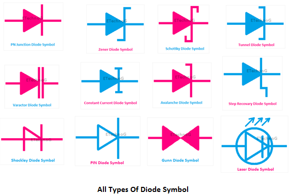
The challenges associated with diode symbols primarily arise from the diversity of diode types. Each specialized diode, such as Zener diodes, Schottky diodes, and LEDs, has a unique symbol variation built upon the basic diode representation. Recognizing these variations is crucial for interpreting complex circuit diagrams accurately. Misinterpreting a symbol can lead to incorrect circuit construction and malfunction.
The basic diode symbol, as mentioned, comprises a triangle pointing towards a line. Zener diodes, used for voltage regulation, have a Z-shaped line added to the basic symbol. Schottky diodes, known for their fast switching speed, feature a curved line connected to the triangle's tip. LEDs, used for light emission, have arrows emanating from the triangle, symbolizing the emitted light. Understanding these variations is akin to learning a new dialect within the language of electronics.
Benefits of standardized diode symbols include clear communication, simplified design, and efficient troubleshooting. Clear communication ensures that designers and technicians understand each other's work, facilitating collaboration and reducing errors. Simplified design allows for faster and more efficient circuit development. Efficient troubleshooting, aided by clear visual representation, allows for quick identification and resolution of circuit faults.
Advantages and Disadvantages of Standardized Diode Symbols
| Advantages | Disadvantages |
|---|---|
| Clear communication | Initial learning curve for diverse symbols |
| Simplified design | Potential for misinterpretation if not carefully studied |
| Efficient troubleshooting | Requires ongoing updates to stay current with new diode types |
Best Practices for Implementing Schematic Symbols for Diodes:
1. Use standard symbols: Adhere to established standards (e.g., IEEE standards) to ensure universal comprehension.
2. Clearly label diode types: Indicate specific diode types (e.g., 1N4001) next to the symbol for accurate component selection.
3. Maintain consistency: Use the same symbol for the same diode type throughout the schematic to avoid confusion.
4. Provide a legend: Include a legend explaining any non-standard or custom symbols used.
5. Use simulation software: Employ circuit simulation software to verify the correct implementation of diode symbols and circuit functionality.
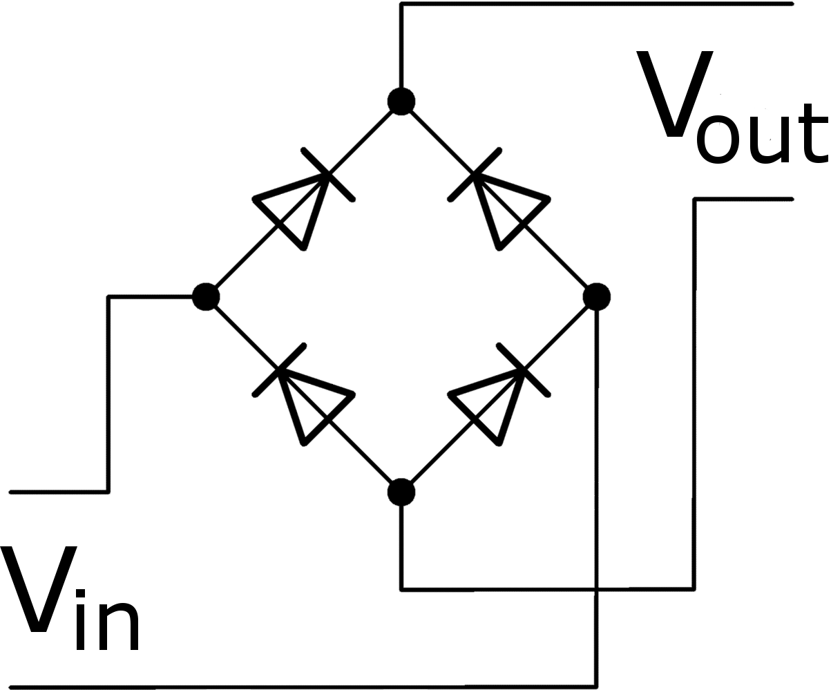
Real Examples: Rectifier circuits, voltage regulators, LED lighting circuits, logic circuits, and signal clipping circuits all employ various diodes and their respective symbols.
Frequently Asked Questions:
1. What is the basic diode symbol? A triangle pointing towards a line.
2. What does the triangle in the diode symbol represent? The anode (positive terminal).
3. What does the line in the diode symbol represent? The cathode (negative terminal).
4. How is a Zener diode symbol different? It has a Z-shaped line added.
5. What does an LED symbol look like? It has arrows emanating from the triangle.
6. Why are standardized symbols important? For clear communication and efficient design.
7. Where can I find a comprehensive list of diode symbols? In electronics textbooks and online resources.
8. How can I learn more about diode symbols and their applications? Explore online tutorials and educational resources.
Tips and Tricks: Use online resources and reference manuals for quick access to diode symbol information. Practice drawing and interpreting various diode symbols to improve your understanding. Utilize circuit simulation software to experiment with different diode types and their behavior in circuits.
In conclusion, schematic symbols for diodes are the essential building blocks of electronic circuit diagrams. Their concise visual representation facilitates clear communication, simplifies design, and enables efficient troubleshooting. Mastering these symbols is paramount for anyone working with electronics, from seasoned professionals to aspiring hobbyists. By understanding the nuances of diode symbols, we unlock the ability to design, build, and troubleshoot circuits effectively. This knowledge empowers us to harness the power of diodes and create innovative electronic solutions. As technology continues to evolve, staying current with new diode types and their symbols will be crucial for success in the ever-expanding world of electronics. Embrace the language of circuits, and explore the endless possibilities that diodes offer.
The enduring appeal of james p sullivan
The curious case of the open eye icon what does it really mean
Fedex stadium seating chart your guide to the best seats in the house


