Mastering Electronic Component Symbols with Charts
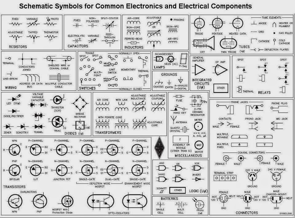
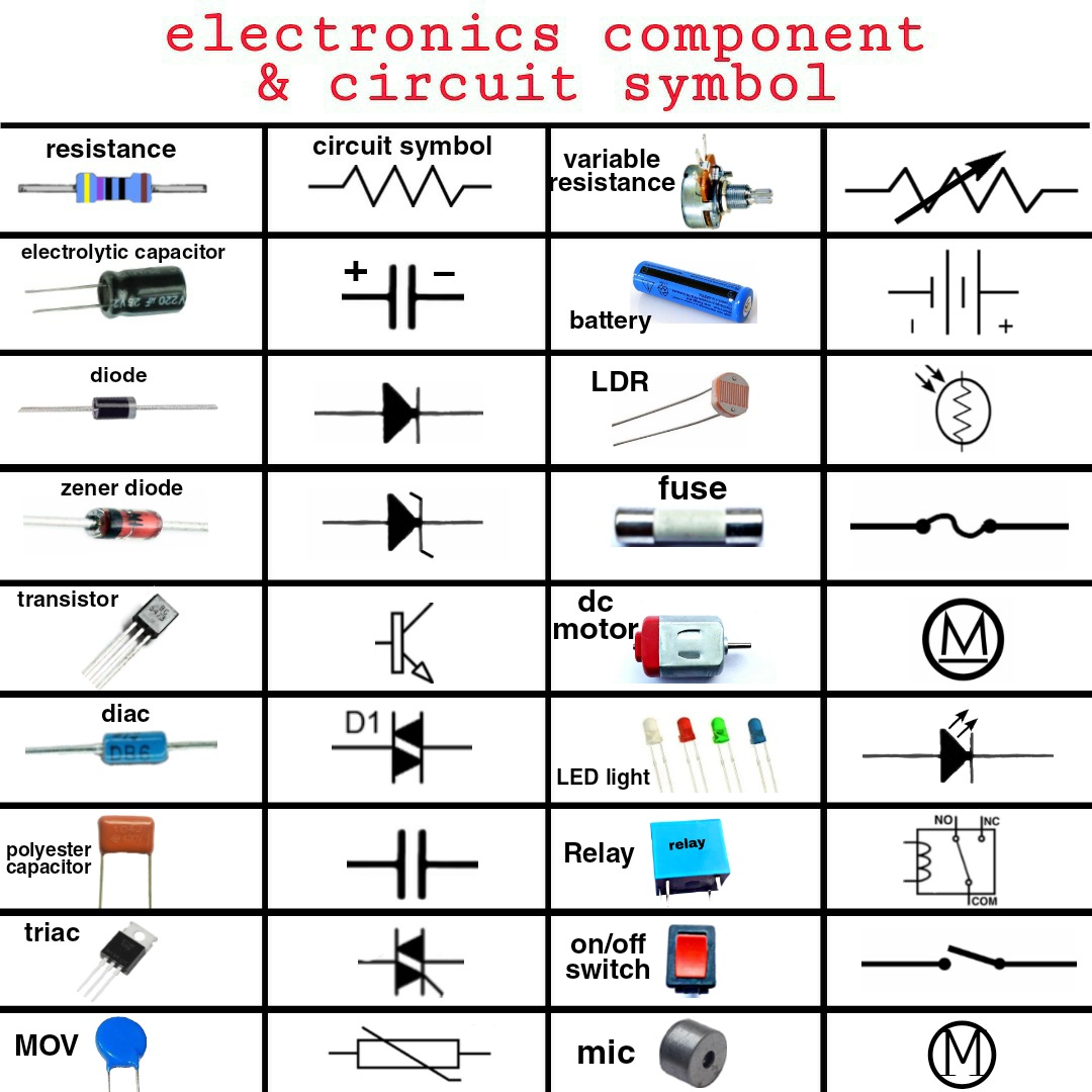
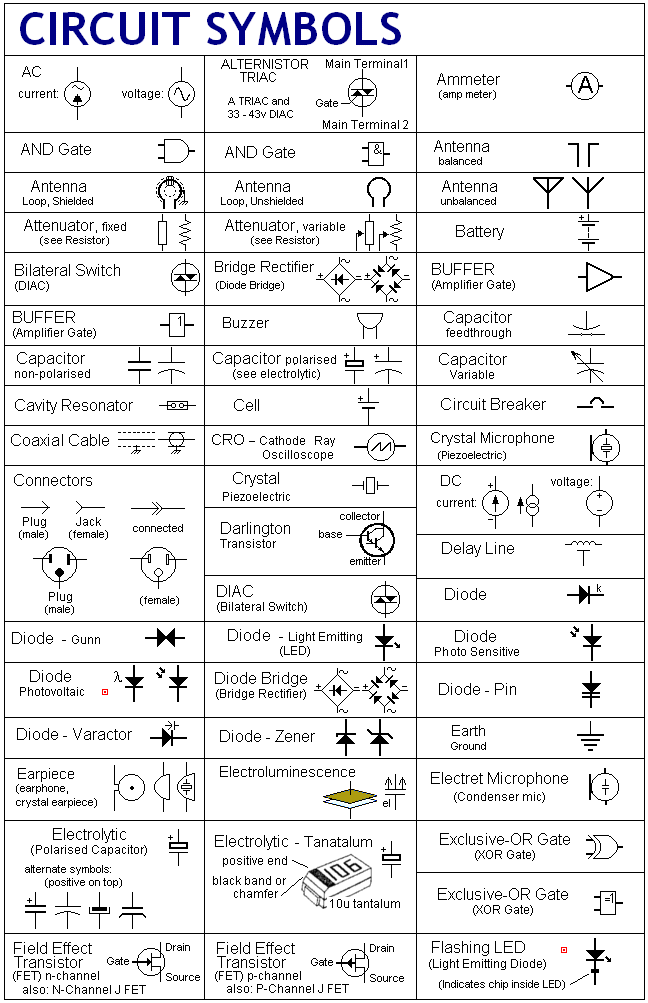
Imagine trying to decipher a complex language without a dictionary. That's the challenge faced by anyone attempting to understand electronic circuits without a grasp of component symbols. These symbols, represented in various formats including electronic component symbol charts, are the fundamental building blocks of circuit diagrams, providing a visual shorthand for the numerous components that make up any electronic system. Whether you're a seasoned engineer or a budding hobbyist, a solid understanding of these symbols is essential.
Electronic component symbols provide a universal language for representing the function of each component within a circuit, from resistors and capacitors to transistors and integrated circuits. These symbolic representations allow engineers and technicians worldwide to communicate circuit designs efficiently. The ability to quickly identify components within a schematic diagram is crucial for troubleshooting, circuit analysis, and design modification. Without a standardized set of symbols, the world of electronics would be a chaotic mess of bespoke representations, hindering collaboration and progress.
The history of electronic component symbols is intertwined with the development of electronics itself. As circuits became more complex, the need for a standardized system of representation became increasingly apparent. Early symbols often resembled the physical appearance of the components they represented. Over time, these symbols evolved into more abstract forms, prioritizing clarity and ease of drawing. The standardization effort led to the creation of various resources, including comprehensive electronic component symbol charts, many of which are available in convenient PDF format for easy access and printing.
These electronic component symbol charts, particularly those available as downloadable PDFs, serve as invaluable resources for anyone working with electronics. They provide a quick reference for identifying components and understanding their function within a circuit. Having a handy PDF version allows for offline access, making it a valuable tool in the lab, classroom, or field. However, navigating the wide array of available charts can sometimes be challenging. Different standards and variations in symbol representation can exist, highlighting the importance of selecting a reliable and up-to-date resource.
One common challenge relates to the evolving nature of electronics. New components are constantly being developed, and keeping electronic component symbol charts updated with these additions can be a significant undertaking. This is why online resources and regularly updated PDF versions are crucial for staying current with the latest symbol representations. Furthermore, understanding the context in which a symbol is used is paramount, as some symbols can have multiple interpretations depending on the specific application within a circuit.
Utilizing accurate and updated electronic component symbols is crucial for effective communication and collaboration in electronics. The benefits extend to various aspects of electronic design, manufacturing, and maintenance.
Effective Communication: Clear and standardized symbols ensure that circuit diagrams are easily understood by engineers and technicians across different teams and even different countries, fostering seamless collaboration and reducing the risk of misinterpretations.
Efficient Troubleshooting: Recognizing component symbols quickly allows technicians to diagnose faults and troubleshoot circuits efficiently, saving valuable time and resources.
Simplified Design and Documentation: Consistent use of standardized symbols simplifies circuit design and documentation, promoting clarity and reducing the likelihood of errors during the design, manufacturing, and testing phases.
Advantages and Disadvantages of Electronic Component Symbol Chart PDFs
| Advantages | Disadvantages |
|---|---|
| Portable and accessible offline | Can become outdated if not regularly updated |
| Printable for easy reference | May not cover all specialized symbols |
| Often free or low-cost | Less interactive than online resources |
Best Practices for Using Electronic Component Symbol Charts:
1. Use a reputable source: Ensure the chart comes from a trusted organization or publisher.
2. Verify the standard: Check that the chart adheres to the appropriate standard (e.g., IEC, ANSI).
3. Keep it updated: Regularly update your chart to include new components and symbols.
4. Context is key: Understand the specific application of a symbol within the circuit.
5. Cross-reference: When in doubt, consult multiple sources to ensure accuracy.
Frequently Asked Questions:
1. Where can I find electronic component symbol charts in PDF format? Many websites and educational resources offer free downloadable PDFs.
2. Are all electronic component symbol charts the same? No, variations exist based on different standards and levels of detail.
3. How often are these charts updated? Updates vary depending on the source; online resources are often more frequently updated.
4. What are the most common symbols used in electronics? Resistors, capacitors, inductors, diodes, and transistors are among the most common.
5. Why is it important to use standardized symbols? Standardization ensures clear communication and prevents misinterpretations in circuit diagrams.
6. Are there any specialized symbols for specific fields of electronics? Yes, specialized symbols exist for areas like digital electronics, power electronics, and RF engineering.
7. Can I create my own electronic component symbol chart? While possible, it's generally recommended to use established standards for clarity and consistency.
8. What software can I use to draw circuit diagrams with these symbols? Numerous software programs, both free and commercial, offer libraries of electronic component symbols.
Tips and Tricks:
Laminate your printed PDF chart for durability.
Organize your charts by category for easy access.
Use a highlighter to mark frequently used symbols.
In conclusion, mastering electronic component symbols is a fundamental skill for anyone involved in electronics. Whether you are designing a complex circuit or simply troubleshooting a simple electronic device, a solid grasp of these symbols, aided by resources like electronic component symbol charts in PDF format or online databases, is invaluable. These resources empower engineers and technicians to communicate effectively, troubleshoot efficiently, and design circuits with confidence. By staying current with the latest symbols and adhering to best practices, you can ensure accuracy and clarity in your electronics projects, laying the foundation for success in this ever-evolving field. Embrace these symbolic representations as the essential language of electronics, and unlock the power to navigate the intricacies of circuits with precision and understanding. Start building your proficiency today, and explore the vast world of electronics with confidence.
Unlocking romance the power of short love phrases
Ford super duty weight everything you need to know
Decoding the dance of flies trout fishing in fall


.jpg)


