Mastering Double-Pole Double-Throw Rocker Switch Wiring
Ever wondered how a single switch can control two separate circuits simultaneously? Or perhaps you're tackling a wiring project and need to understand the intricacies of a double-pole, double-throw (DPDT) rocker switch? This comprehensive guide will demystify the DPDT rocker switch diagram, equipping you with the knowledge to confidently wire, troubleshoot, and utilize these versatile switches.
The DPDT rocker switch, a staple in electrical systems, offers a powerful mechanism for controlling two distinct circuits. Unlike a single-pole switch that simply opens or closes one circuit, the DPDT rocker switch provides the capability to switch two circuits simultaneously, either independently or in conjunction. This makes them ideal for applications requiring complex switching operations.
Understanding the functionality of a DPDT rocker switch begins with deciphering its schematic representation, commonly known as the DPDT rocker switch wiring diagram. This diagram visually depicts the switch's internal connections and how they relate to the external circuits. By mastering this diagram, you can confidently tackle any wiring project involving a DPDT switch.
While the exact origins of the DPDT rocker switch are difficult to pinpoint, its development is intrinsically linked to the evolution of electrical switching technology. As electrical systems became more complex, the need arose for switches capable of handling multiple circuits. The DPDT rocker switch emerged as a solution, offering the flexibility and control needed for these evolving systems. Its importance lies in its ability to manage complex switching scenarios with a simple, user-friendly interface.
One common issue encountered with DPDT rocker switches involves misinterpreting the wiring diagram, leading to incorrect connections and malfunctioning circuits. Another challenge can arise from selecting the wrong type of DPDT switch for a specific application. Understanding the different variations and their respective ratings is crucial for successful implementation.
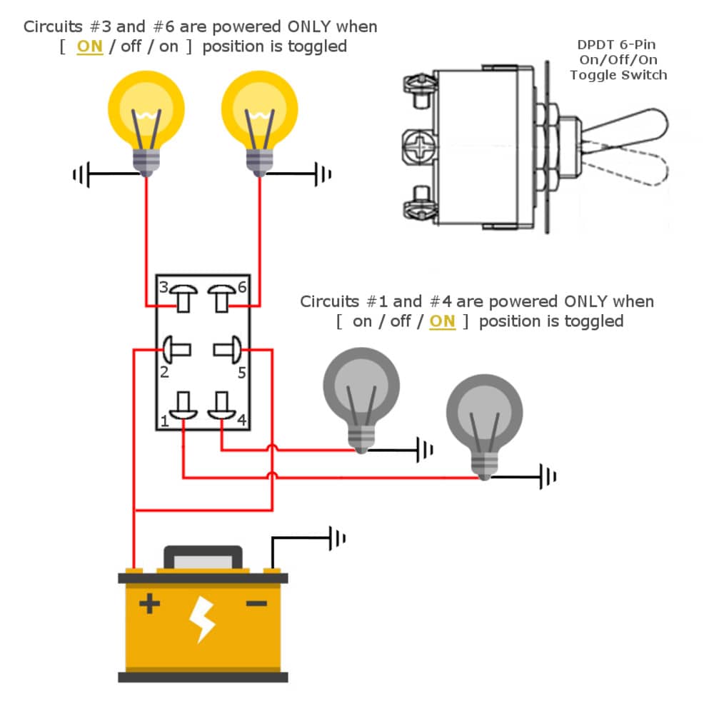
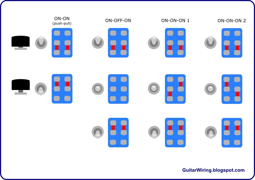
The DPDT rocker switch wiring diagram depicts six terminals: two common terminals, two normally open terminals, and two normally closed terminals. The common terminals serve as the input for the two circuits being controlled. The normally open terminals are connected to the circuit when the switch is flipped in one direction, while the normally closed terminals are connected when the switch is in the opposite position.
One benefit of using DPDT rocker switches is their versatility in controlling multiple circuits simultaneously. For example, a single DPDT switch can be used to control both a light fixture and a ceiling fan. Another advantage is their ability to reverse polarity, useful in applications like reversing the direction of a DC motor. Finally, DPDT switches provide a simple solution for switching between two different power sources.
Before starting any wiring project, always disconnect the power supply. Next, carefully study the DPDT rocker switch wiring diagram to identify the common, normally open, and normally closed terminals. Connect the wires according to the diagram, ensuring proper connections for each circuit. After wiring, thoroughly test the switch to verify its functionality.
Advantages and Disadvantages of DPDT Rocker Switches
| Advantages | Disadvantages |
|---|---|
| Versatile control of multiple circuits | Can be more complex to wire than simpler switches |
| Ability to reverse polarity | Slightly higher cost compared to SPST switches |
| Switching between different power sources | Requires careful attention to the wiring diagram |
Best practices for implementing DPDT switches include using appropriate wire gauges, securing all connections properly, and using a multimeter to verify correct wiring.
Real-world examples include using DPDT switches in lighting control systems, automotive applications, and industrial machinery.
Challenges related to DPDT switches may involve troubleshooting faulty wiring or selecting the correct switch for specific current and voltage requirements. Solutions involve careful inspection of the wiring diagram and consulting manufacturer specifications.
Frequently asked questions cover topics such as wiring diagrams, troubleshooting, and choosing the right DPDT switch.
Tips and tricks include using color-coded wires for easier identification and double-checking connections before energizing the circuit.
In conclusion, mastering the DPDT rocker switch diagram empowers you to harness the full potential of these versatile switches. By understanding their functionality, applications, and wiring intricacies, you can confidently tackle a wide range of electrical projects. The DPDT rocker switch, with its ability to control multiple circuits, offers a powerful solution for complex switching needs. Whether you're wiring a lighting system, controlling a motor, or switching between power sources, the DPDT rocker switch provides the flexibility and control necessary for a multitude of applications. Take the time to familiarize yourself with its intricacies, and you’ll discover a powerful tool for simplifying your electrical projects.
Unmasking the mystery who is carl weathers wife jennifer
Can psg conquer group f in this years champions league
Soaring expressions the art of drawings with wings tattoos angel halo


