Decoding Circuit Switches Symbols Like a Pro
Ever stared at a circuit diagram and felt like you were deciphering hieroglyphics? Those little symbols representing switches are more than just squiggles; they're the key to understanding how electricity flows and controls your devices. Let's dive into the world of circuit switch symbols and unlock their secrets.
Imagine trying to build a house without blueprints. Chaos, right? Circuit diagrams are the blueprints of electronics, and switch symbols are crucial components. They provide a visual language that allows engineers and hobbyists to communicate and understand complex electrical designs. From the simple on/off switch in your bedroom to the intricate circuitry of a computer, these symbols are essential for design, troubleshooting, and collaboration.
The representation of switches in circuit diagrams has evolved over time, driven by the need for standardization and clarity. Early diagrams might have used more literal depictions, but as electronics became more complex, simplified and standardized symbols emerged. These symbols, often defined by international standards like IEC 60617, ensure that anyone, regardless of their native language, can understand the function of a switch within a circuit.
These symbols aren't just about convenience; they're about safety and functionality. A misplaced or misrepresented switch symbol can lead to faulty circuits, malfunctioning devices, or even dangerous electrical hazards. Understanding the meaning of each switch symbol is paramount for anyone working with electronics, from designing a simple circuit to troubleshooting complex systems.
Without standardized switch symbols, the world of electronics would be a confusing mess. Imagine trying to collaborate on a project with someone who uses different symbols for the same components. The potential for errors and misunderstandings would be enormous. These symbols provide a universal language, enabling efficient communication and collaboration among engineers, technicians, and enthusiasts worldwide.
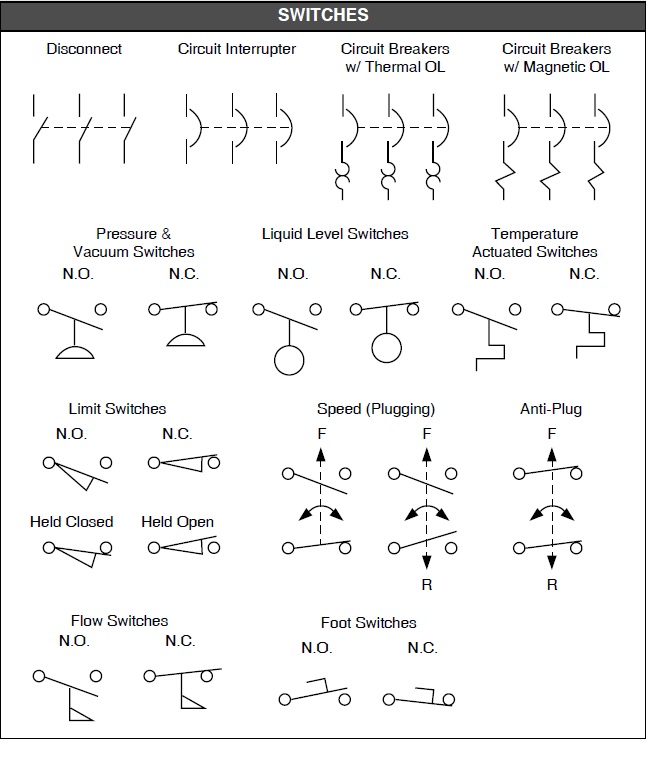
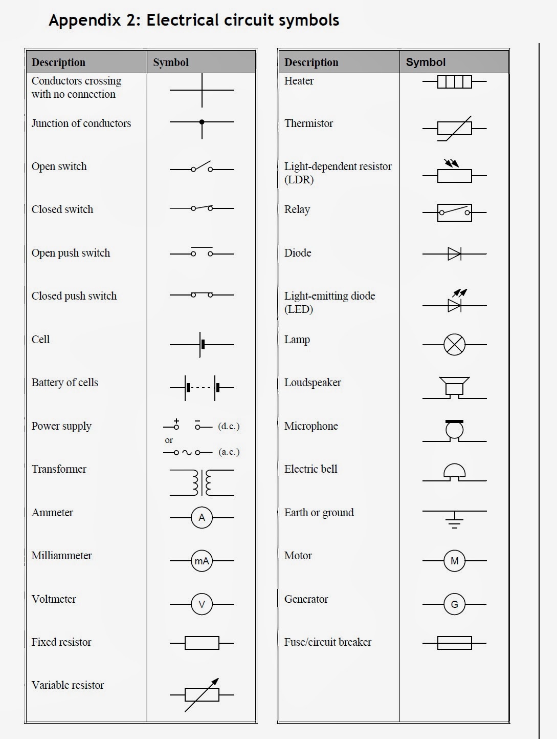
A single-pole single-throw (SPST) switch symbol represents a simple on/off switch. It looks like a break in a line with a small spur coming off of it. A single-pole double-throw (SPDT) switch symbol shows a line branching into two paths, indicating its ability to connect the input to either of two outputs. Push-button switch symbols often resemble a small rectangle with a line pushing down on it, visually representing the action of pressing the button. These graphical representations provide instant recognition of the switch's function.
Understanding switch configurations is fundamental in circuit analysis. A basic SPST switch controls a single circuit, while an SPDT switch can select between two different circuits. More complex switches, like double-pole double-throw (DPDT) switches, allow for simultaneous control of multiple circuits. These nuanced functions are clearly communicated through their respective symbols.
One of the core benefits of standardized switch symbols is their ability to simplify complex circuit diagrams. By using easily recognizable symbols, engineers can quickly grasp the overall function of a circuit without having to decipher complex descriptions. This visual clarity makes troubleshooting and modification significantly easier.
Another significant advantage is the universal understanding they facilitate. This common language breaks down communication barriers between engineers from different backgrounds and countries, enabling seamless collaboration on international projects. This shared understanding accelerates development and reduces the risk of misinterpretations.
Furthermore, these symbols aid in the efficient design of new circuits. Engineers can quickly and effectively lay out their circuit plans using these symbols, experimenting with different configurations and ensuring the desired functionality before physical implementation. This symbolic representation saves time and resources, streamlining the design process.
Advantages and Disadvantages of Standardized Switch Symbols
| Advantages | Disadvantages |
|---|---|
| Clarity and ease of understanding | Requires learning the symbols |
| Universal language for engineers | Can be overwhelming for beginners |
| Efficient circuit design and troubleshooting | Subtle differences between symbols can be confusing |
Best practices for using switch symbols include ensuring consistency in their orientation and placement within a diagram, using labels to clarify their function when necessary, and adhering to recognized standards like IEC 60617 to avoid ambiguity. Implementing these practices guarantees clear and understandable circuit diagrams.
In conclusion, the seemingly simple symbols representing switches in circuit diagrams are vital for effective communication, design, and troubleshooting in the world of electronics. Their standardized nature allows for a universal language among engineers, simplifies complex designs, and ensures the safety and functionality of electrical systems. From the basic on/off switch to complex switching networks, understanding these symbols is crucial for anyone working with circuits. So, next time you see a circuit diagram, take a moment to appreciate the power and significance of those small but essential switch symbols. They are the silent conductors of the electrical world, orchestrating the flow of power and enabling the technology that shapes our modern lives.
Decoding the dog holding its nose meme
Winning the war of words crafting the perfect comeback
The enduring influence of chicano gangster cursive style


