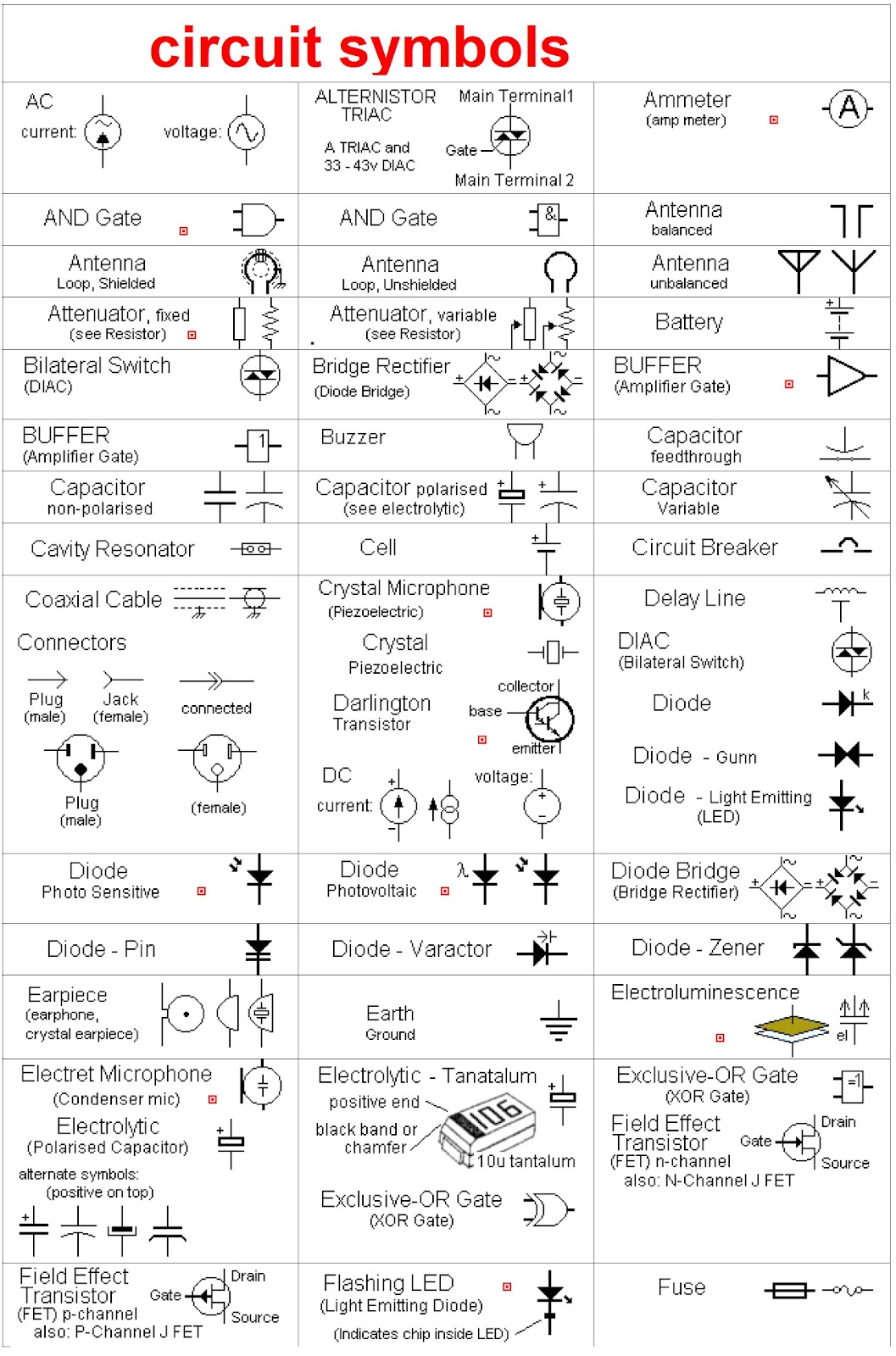
Decoding Circuit Diagrams AC and DC Schematic Symbols
Imagine trying to read a book written in a language you don't understand. Frustrating, right? That's what it's like trying to decipher an electrical circuit diagram without knowing the meaning of the symbols within it. AC and DC schematic symbols are the fundamental language of circuit diagrams, allowing engineers and hobbyists alike to communicate and understand the flow of electricity within a system.
These symbols, seemingly simple lines and shapes, represent complex electrical components and their functions. They are essential for designing, building, and troubleshooting circuits, whether it's a simple flashlight or a complex power grid. Without a clear understanding of these symbolic representations, navigating the world of electronics becomes an impossible task.
AC (alternating current) and DC (direct current) schematic symbols, while sharing some similarities, also have distinct representations that reflect the different nature of these currents. AC, characterized by its constantly changing direction, uses symbols that often depict sinusoidal waves or circular loops. DC, with its steady, unidirectional flow, employs symbols that are often simpler and more linear.
Mastering these symbols is not just about memorization; it's about understanding the underlying principles they represent. This understanding opens the door to designing and analyzing circuits with confidence, allowing you to bring your electrical projects to life.
The historical development of these symbols is intertwined with the evolution of electrical engineering itself. From early crude representations to the standardized symbols we use today, these visual shorthand notations have played a crucial role in advancing our understanding and application of electricity.
Early schematic symbols were often crude representations of the physical components themselves. As the field of electronics grew more complex, the need for standardized symbols became apparent. Organizations like the IEEE (Institute of Electrical and Electronics Engineers) played a crucial role in developing and standardizing these symbols, ensuring clear communication across the industry.
The importance of standardized AC and DC schematic symbols cannot be overstated. They provide a universal language for electrical engineers, technicians, and hobbyists, enabling them to share designs, troubleshoot problems, and collaborate effectively. This standardization also promotes safety, ensuring that everyone involved in a project understands the circuit's functionality and potential hazards.
A simple example of a DC symbol is the battery symbol, represented by a series of alternating long and short lines. The longer line indicates the positive terminal, while the shorter line represents the negative terminal. An example of an AC symbol is the AC voltage source symbol, often depicted as a circle with a sinusoidal wave inside.
Benefits of using standard symbols include enhanced communication, reduced design errors, and improved troubleshooting efficiency. Standardized symbols allow for clear and concise circuit diagrams, minimizing ambiguity and misinterpretations. This leads to fewer design errors and simplifies the process of identifying and rectifying problems within a circuit.
A checklist for understanding schematic symbols could involve verifying component identification, confirming polarity markings, and checking connections between components. This checklist helps ensure accurate interpretation of the diagram and reduces the risk of errors during circuit construction.
Advantages and Disadvantages of Standardized Schematic Symbols
| Advantages | Disadvantages |
|---|---|
| Improved Communication | Requires Learning |
| Reduced Errors | Can Be Complex for Beginners |
| Enhanced Troubleshooting | Variations Across Different Standards |
Five best practices for implementing schematic symbols include using the correct symbol for each component, clearly labeling all components, ensuring proper polarity markings, maintaining a consistent style throughout the diagram, and using software tools for creating and managing diagrams.
Real-world examples of AC and DC schematic symbols can be found in countless electronic devices, from simple household appliances to complex industrial machinery. The power supply of a computer, the circuitry within a smartphone, and the control systems of an automobile all rely on these symbols to represent the intricate network of electrical components within.
One common challenge is the sheer number of symbols to learn and remember. Solutions include using reference guides, practicing regularly, and utilizing software tools with built-in symbol libraries.
FAQs about AC and DC schematic symbols often revolve around identifying specific symbols, understanding their meaning, and differentiating between AC and DC representations. These questions highlight the importance of continuous learning and practice in mastering the language of circuit diagrams.
Tips and tricks for working with schematic symbols include using online resources, creating flashcards, and participating in online forums and communities to share knowledge and learn from others' experiences.
In conclusion, understanding AC and DC schematic symbols is fundamental to anyone working with or interested in electronics. These symbols are the language of circuit diagrams, enabling us to design, build, and troubleshoot electronic systems effectively. Mastering these symbols empowers us to navigate the complex world of electronics with confidence and precision. Whether you are a seasoned engineer or a curious beginner, taking the time to learn and understand these symbols is an investment that will pay dividends in your electronic endeavors. They are more than just symbols; they are the keys to unlocking the power of electricity. So, delve into the world of schematic symbols and unlock your potential in the fascinating realm of electronics. By continuing to learn and practice, you can become proficient in interpreting and utilizing these symbols, opening up a world of possibilities in the field of electronics.
Inking obsession unraveling the mystery of bestselling drawing pens
Spinning dreams exploring the allure of la ruleta de la fortuna participar
Conquering roads your guide to the gmc yukon xl slt


